The connecting rod is the link which
transmits forces between the piston and the crankshaft. Connecting rods must be strong enough to
remain rigid under load and yet be light enough to reduce the inertia forces
which are produced when the rod and piston stop, change direction, and start
again at the end of each stroke.
There are three types of connecting-rod
assemblies:
- The master-and-articulated-rod assembly
- The plain-type connecting rod
- The fork-and-blade connecting rod
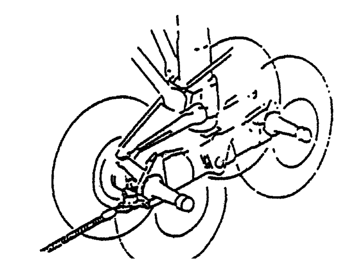
The master-and-articulated-rod assembly
The master-and-articulated rod assembly is
commonly used in radial engines. In a
radial engine the piston in one cylinder in each row is connected to the
crankshaft by a master rod. All other
pistons in the row are connected to the master rod by an articulated rod. The articulated rods are constructed of
forged steel alloy in either the I- or H-shape, denoting the cross-sectional
shape. Bronze bushings are pressed into
the bores in each end of the articulated rod to provide knuckle-pin and piston-pin
bearings.
The master rod serves as the connecting
link between the piston pin and the crankpin.
The crankpin end, or the ‘big end’
contains the crankpin or master rod bearing.
Flanges around the big end provide for the attachment of the articulated
rods. The articulated rods are attached
to the master rod by knuckle pins, which are pressed into holes in the master
rod flanges during assembly. A plain
bearing, usually called a piston-pin bushing, is installed in the piston end of
the master rod to receive the piston pin.

Plain-type connecting rods
Plain-type connecting rods are used in
in-line and opposed engines. The end of
the rod attached to the crank pin is fitted with a cap and a two-piece bearing. The bearing cap is held on the end of the rod
by bolts or studs. To maintain proper
fit and balance, connecting rods should always be replaced in the same cylinder
and in the same relative position.
.jpg)
The fork-and-blade rod

The fork-and-blade rod assembly is used
primarily in V-type engines. The forked
rod is split at the crankpin end to allow space for the blade rod to fit
between the prongs. A single two-piece
bearing is used on the crankshaft end of the rod.


.jpg)